Two standard surfaces are available: slottedsmooth and anti-skid. Anti-skid is the ideal choice when safe walking conditions are important. Dieformed teeth in the transverse ribs give you 360° of shoe-gripping traction even when the grating is wet, oily, muddy, or icy.
Punched Interlock Grating has an open area of 42% for 9' grating and 35% for 6' grating. This prevents dirt, debris, ice, and snow from building up on the surface and allows light and air to pass through. United Interlock steel grating is made from pre-galvanized steel which conforms to a G-90 thickness designation per ASTM A653. The aluminum grating is made from type 5052 aluminum with a thickness of 0.080'.
Unpunched smooth surface grating is also available for special applications.
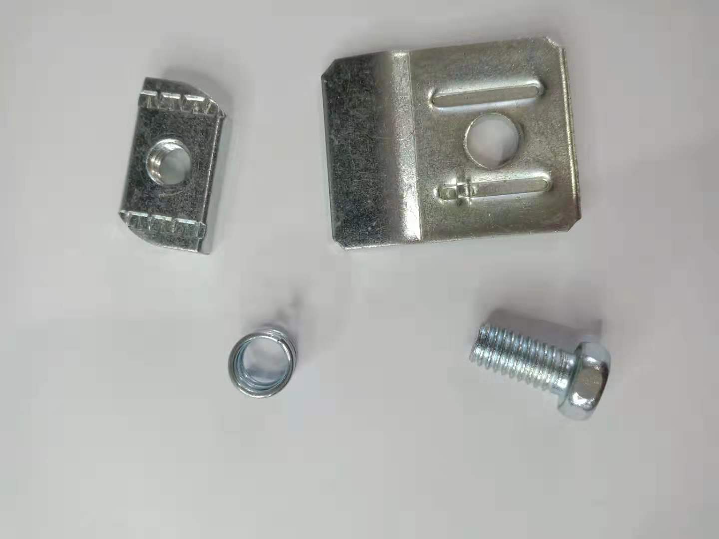
Sep 14, 2017 Unistrut nuts are available with a variety of hole sizes, to accept a range of hex head cap screw (hex bolt) sizes. There are even spring nuts with bolts built in; these are called stud nuts, and they can make the assembly process very quick and efficient.
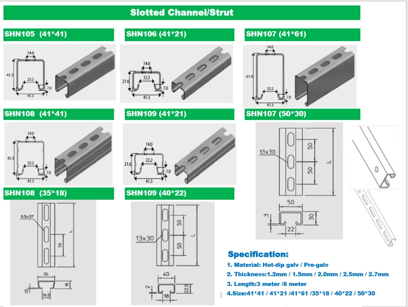
Unistrut Sizes
Zinc Plated Carbon Steel Combo Strut Nut Washer 1100 Lb Capacity, 0.375' Bolt, 1 Hole, Used with Cooper B Line Channel & Strut (All Sizes Except B62 & B72) MSC# 82610510 Cooper B-Line (NW528 ZN). Channel To Beam U-Bolt Clamp, 3' Length On Plate, 2-1/2' Width On Plate, 3-3/4' Length Of U-Bolt- Pack Of 5 - Product details Product Dimensions: 0.2 x 0.1 x 0.1 inches; 13.3 ounces.
One of the most common requests we receive concerns drawings for Unistrut support structures.

The tables below contain downloadable standard design detail drawings for typical Unistrut applications–medical supports, rooftop walkways, and ceiling grid systems.
Please Note: Drawings below are generic details to show design intent only. The drawings will help you gain a better understanding of engineered system design options, but these drawings are not intended for construction purposes because each system is application specific. We are currently working on developing additional standard details for other systems, but at this time, we only offer resources to support the development of medical supports, rooftop walkways, and ceiling grid structures.
For interior applications, rooms will more than likely contain suspended MEP and we may need to make modifications to an existing design to accommodate mechanical systems such as plumbing, HVAC, and electrical. Contact Unistrut Service Company for pricing on site specific engineered system drawings.
Medical Support Structure Standard Detail Drawings

The tables below contain downloadable standard design detail drawings for typical Unistrut medical support structure applications.
Please Note: Drawings below are generic details to show design intent only. The drawings will help you gain a better understanding of engineered medical support structure design, but they are not intended for construction purposes because each system is application specific.
| *Unistrut Cath Lab Support Structure Standard Detail Drawings | ||
|---|---|---|
| *Drawings are generic details to show design intent only. Contact Unistrut Service Company for pricing on site specific drawings. ** There are no standard details for Cath Lab Supports attached to bar joists as bar joists are typically insufficient to handle the load. | ||
| Concrete Applications | **Steel Beam Applications | |
| Concrete Beams | Concrete With Metal Deck | Wide Flange Beam Structure |
| Ceiling Rails Parallel to Beams DWG | Ceiling Rails Parallel to Metal Deck DWG | Ceiling Rails Parallel to Beams DWG |
| Ceiling Rails Perpendicular to Beams DWG | Ceiling Rails Perpendicular to Metal Deck DWG | Ceiling Rails Perpendicular to Beams DWG |
| *Unistrut Exam Light Support Structure Standard Detail Drawings | |||
|---|---|---|---|
| *Drawings are generic details to show design intent only. Contact Unistrut Service Company for pricing on site specific drawings. | |||
| Joist Applications | Concrete Applications | ||
| Bar Joist Structure DWG | Concrete Beams DWG | Flat Concrete Deck DWG | Concrete With Metal Deck DWG |
| *Unistrut Three and Four Rail Support Structures | |
|---|---|
| *Drawings are generic details to show design intent only. Contact Unistrut Service Company for pricing on site specific drawings. | |
| Joist Applications | Concrete Applications |
| Three Rail Bar Joist Structure NA | Three Rail Concrete Deck Support Structure DWG |
| Four Rail Bar Joist Structure DWG | Four Rail Concrete Deck Support Stucture DWG |
| *Unistrut Injector, Monitor, and Surgical Light Support Structures | |||
|---|---|---|---|
| *Drawings are generic details to show design intent only. Contact Unistrut Service Company for pricing on site specific drawings. | |||
| Joist Applications | Concrete Applications | ||
| Bar Joist Structure DWG | Concrete Beams DWG | Flat Concrete Deck DWG | Concrete With Metal Deck DWG |
Unistrut Size Chart
Rooftop Walkway Standard Detail Drawings

The tables below contain downloadable standard design detail drawings for typical Unistrut rooftop walkway applications.
Please Note: Drawings below are generic details to show design intent only. The drawings will help you gain a better understanding of engineered rooftop walkway design, but they are not intended for construction purposes because each system is application specific.
Your rooftop walkway system will likely include sections that are less than 10′ in length, and we may need to make modifications to an existing design to accommodate mechanical systems such as rooftop HVAC units, vent stacks, etc. Contact Unistrut Service Company for pricing on site specific engineered system drawings.
| Unistrut Rooftop Walkway Standard Detail Drawings | |||
|---|---|---|---|
| *Drawings are generic details to show design intent only. Contact Unistrut Service Company for pricing on site specific drawings. | |||
| Description | Length | .DWG | |
| One Handrail, Grating Parallel to Seam | 10' | Download DWG | Download PDF |
| One Handrail, Grating Perpendicular to Seam | 10' | Download DWG | Download PDF |
| Two Handrails, Grating Parallel to Seam | 10' | Download DWG | Download PDF |
| Two Handrails, Grating Perpendicular to Seam | 10' | Download DWG | Download PDF |
| No Handrail, Grating Parallel to Seam | 10' | Download DWG | Download PDF |
| No Handrail, Grating Perpendicular To Roof | 10' | Download DWG | Download PDF |
| One Handrail, Flat Roof Application | 10' | Download DWG | Download PDF |
| Two Handrails, Flat Roof Application | 10' | Download DWG | Download PDF |
| No Handrail, Flat Roof Application | 10' | Download DWG | Download PDF |
Unistrut Ceiling Grid Standard Detail Drawings
The tables below contain downloadable standard design detail drawings for typical Unistrut ceiling grid applications.
Please Note: Drawings below are generic details to show design intent only. The drawings will help you gain a better understanding of engineered ceiling grid design, but they are not intended for construction purposes because each system is application specific.

Bolt Size For Unistrut

| Unistrut Standard Detail 4' x 4' Grid Section Drawings* | ||||
|---|---|---|---|---|
| Application | Corner Connections | Duty Rating | .DWG | |
| Concrete Deck | Single Plane | Standard Duty | Download DWG | Download PDF |
| Heavy Duty | Download DWG | Download PDF | ||
| Concrete Deck | Two Plane Lapped Grid | Standard Duty | Download DWG | Download PDF |
| Heavy Duty | Download DWG | Download PDF | ||
| Concrete Deck /Corrugated Metal | Single Plane | Standard Duty | Download DWG | Download PDF |
| Heavy Duty | Download DWG | Download PDF | ||
| Concrete Deck /Corrugated Metal | Two Plane Lapped Grid | Standard Duty | Download DWG | Download PDF |
| Heavy Duty | Download DWG | Download PDF | ||
| Beams/Joist | Single Plane | Standard Duty | Download DWG | Download PDF |
| Heavy Duty | Download DWG | Download PDF | ||
| Beams/Joist | Two Plane Lapped Grid | Standard Duty | Download DWG | Download PDF |
| Heavy Duty | Download DWG | Download PDF | ||
| *Drawings are generic details to show design intent only. Contact Unistrut Service Company for pricing on site specific drawings. | ||||
| Unistrut Standard Detail 6' x 6' Grid Section Drawings* | ||||
|---|---|---|---|---|
| Application | Corner Connections | Duty Rating | .DWG | |
| Concrete Deck | Single Plane | Standard Duty | Download DWG | Download PDF |
| Heavy Duty | Download DWG | Download PDF | ||
| Concrete Deck | Two Plane Lapped Grid | Heavy Duty | Download DWG | Download PDF |
| Concrete Deck /Corrugated Metal | Single Plane | Standard Duty | Download DWG | Download PDF |
| Heavy Duty | Download DWG | Download PDF | ||
| Concrete Deck /Corrugated Metal | Two Plane Lapped Grid | Heavy Duty | Download DWG | Download PDF |
| Beams/Joist | Single Plane | Standard Duty | Download DWG | Download PDF |
| Heavy Duty | Download DWG | Download PDF | ||
| Beams/Joist | Two Plane Lapped Grid | Heavy Duty | Download DWG | Download PDF |
| *Drawings are generic details to show design intent only. Contact Unistrut Service Company for pricing on site specific drawings. | ||||